Thank you for purchasing my 3D printed Mercury Windtunnel kit. It's a fairly simple kit, but because it's not a professionally-made, boxed model kit, it's can be a little more challenging to assemble.
I included a small tube of super glue with the kit which should be sufficient to finish the model. Screw the red plastic tip on until it pierces the cap of the tube. For best results, lightly sand any parts that will be glued for best adhesion.
Note that the silver parts all have a seam on one side, an artiifact of the 3D printing process. Take care to align all of these seams on the same side of the model so they'll all be on the same side of the model and an be turned to the back when displayed.
The parts were printed in PLA, which can be sanded and painted if desired. Avoid placing the model near a heat source or sunny window, as it can warp or sag above 80F / 26C.
Step 1:
Glue the top of the capsule to the body of the capsule. There are no registrration marks so you'll have to center it yourself.
Step 2:
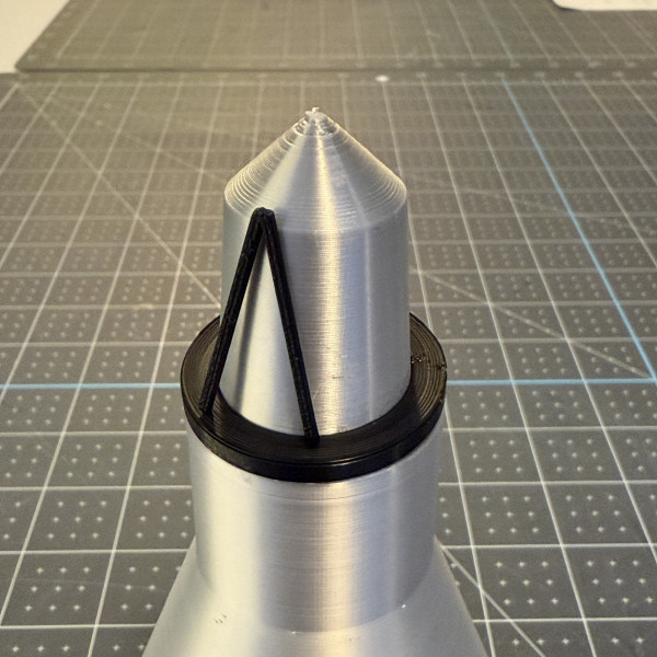
Assembling the base of the LES truss that fits over the top of the capsule. Slide the largest black ring over the top and seat it atop the capsule. With the "V" shape upside down, add a small amount of glue to each leg and affix it to the base and lean it up against the ttop of the capsule. Be sure to fit the legs about midway between the inner and outer edge of the bottom ring. Repeat for all 6 "V" truss pieces. Let dry.
Step 3:
Glue the middle-sized ring to the top of the 6 V truss pieces you just applied. Let dry.
Step 4:
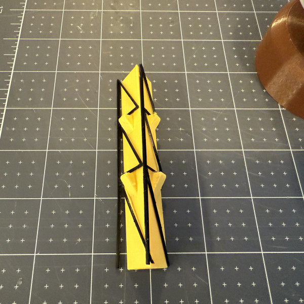
This is the most challenging part of the assembly process. The three tall truss pieces of the LES should now be assembled. There are two distinct sides to the pieces. One one side you can see the 3D print lines, the other is more of a sand-paper like texture. My preference is the sand-paper texture side out. I included a yellow jig that should help get the initial two sides of the truss assembled. It's a very delicate structure and there are only three points of contact. You may need to trim the long, bottom leg to fit. Let this dry.
Step 4:
Without the yellow jig, glue the last piece of the tall LES truss to the other two completing the structure. Once dry, glue the bottom three points to the top ring of the lower truss. Let dry.
Step 5:
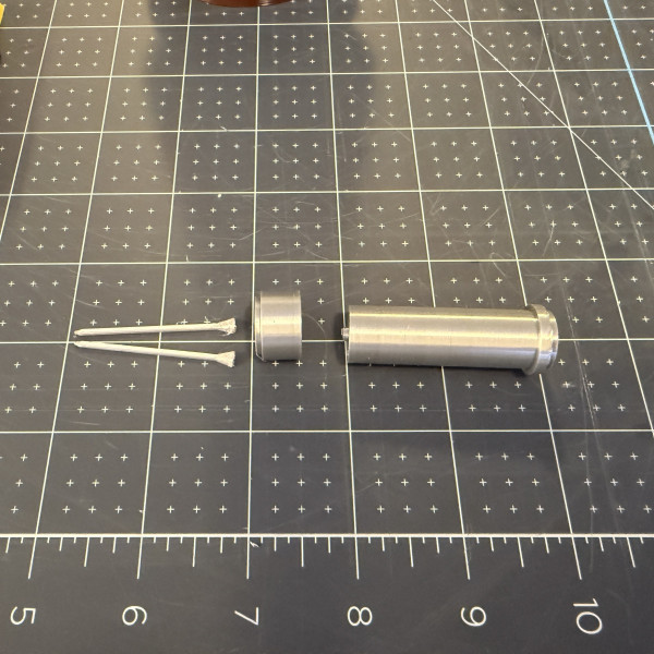
Assemble the top rocket component of the LES. Glue two halves of the top tip together. Make sure the bottom is smooth with a bit of sandpaper. Assemble the two silver pieces of the top of the LES, there is a knob at the top of the larger piece that fits into the bottom piece. Assemble and glue these together. Affix the narrow tip you assembled previously and glue to the top center of the LES engine assembly.
Step 6:
Insert the base of the silver LES assembly into the top ring of the LES truss and glue. Let dry.
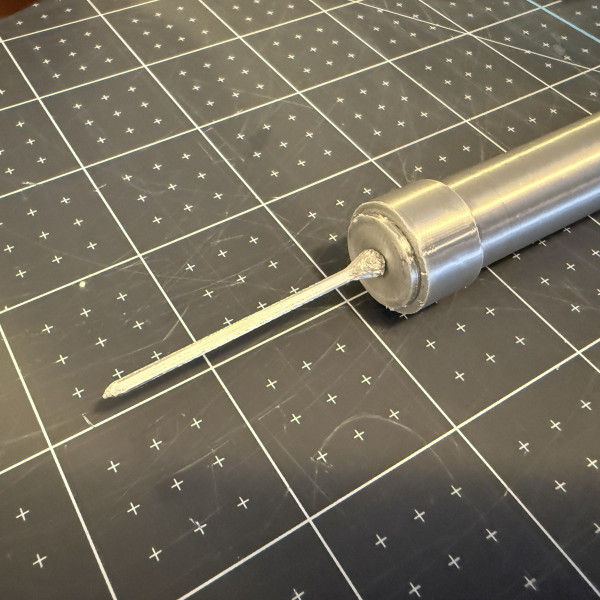
Step 7:
Invert the entire assembly and glue in the center of the bottom of the silver LES top the long narrow engine piece.
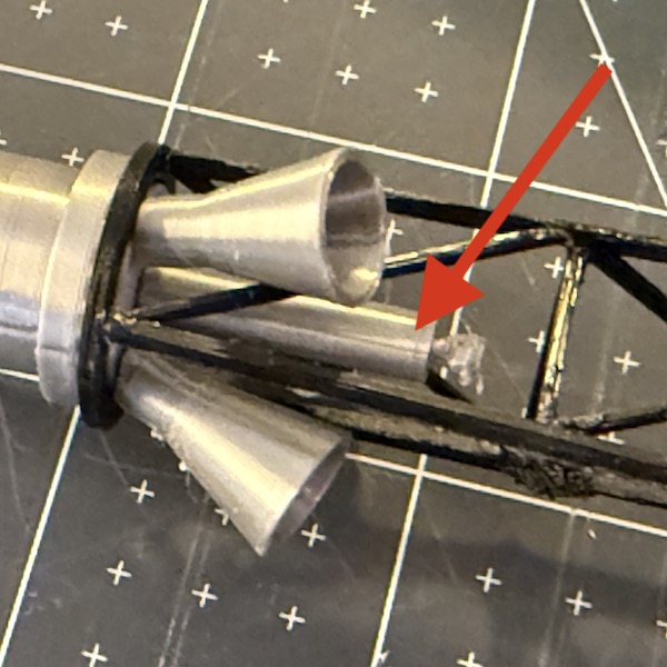
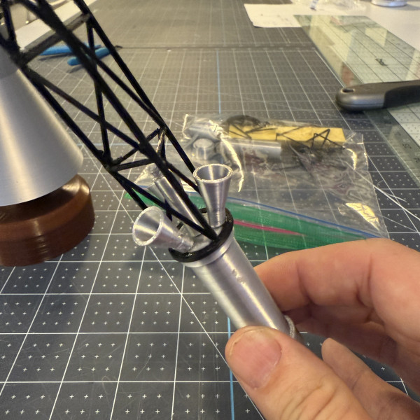
Step 8;
Now we attach the three angled nozzles to the base of the silver LES top. If you can, prop the entire structure at an angle so the angled structure of the bottom of the nozzle piece can be glued on vertically for easier glueing. Turn and repeat for each of the nozzles.
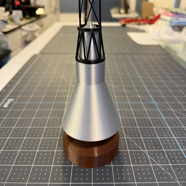
Step 9:
Glue the capsule to the base and slide the truss onto the top. That's it!